 |
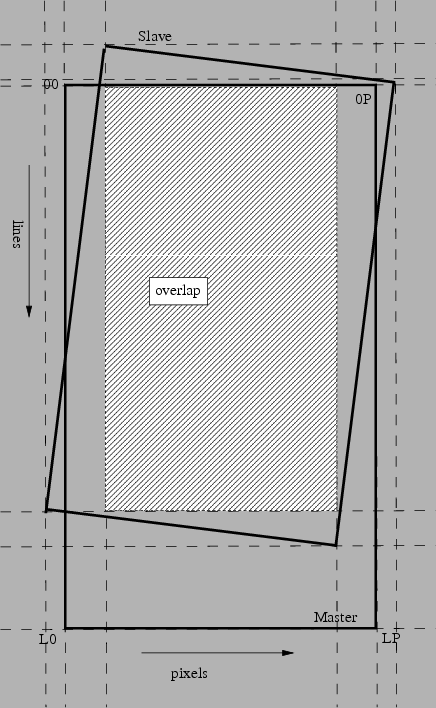
The overlap between slave and master is computed as indicated in figure 21.1.
Interpolation is done with a kernel function such as, e.g., a truncated sinc function. First a look-up table is computed for the selected interpolation kernel. This table evaluates the kernel every 1/INTERVAL = 0.05 positions, which should be accurate enough.
Interpolation is independent for azimuth and range direction. For all points in the overlap between master and slave, the co-registration polynomial is evaluated.
If the total image does not fit in the memory, processing is done in buffers.
The azimuth spectrum of the complex SLC data is not centered around zero in general. The location of the peak in the spectrum is given by a polynomial in the header file.
For a correct interpolation, either the spectrum of the data has to be shifted to zero, or the interpolation kernel. We shift the kernel in azimuth. In range the spectrum is centered (for satellite data).
  A simple derivation shows how the kernel should be shifted.
  Suppose we have a signal:

  s(x)=exp(i*2pi*x*fdc/prf),

  and we want to interpolate this signal at xi=5.1 with a triangular
  kernel k(x_0), such that the interpolated signal

  s_i(xi)=sum(k(x_0).*s(x_1)).

  This means with x_0=[-0.1,0.9] and x_1=[5,6] (as implemented in
  Doris), the kernel is formed as

  k(x_0)=triangle(x_0) = [0.9,0.1]

  and we shift this with the MINUS sign by multiplication with
  t(x_0)=exp(-i*2p*x_0*fdc/prf).

  Then the interpolated value at 5.1 equals:

  s_i(5.1) = k(-0.1)*t(-0.1)*s(5) + k(0.9)*t(0.9)*s(6)
           = 0.9*exp(-i*2pi*-0.1*fdc/prf)*exp(i*2pi*5*fdc/prf) +
             0.1*exp(-i*2pi*0.9*fdc/prf)*exp(i*2pi*6*fdc/prf)
           = exp(i*2pi*5.1*fdc/prf)
	   = s(5.1);// perfect interpolation!

  On the contrary, when we use the PLUS, it follows that

  s_i(5.1) = 0.9*exp(i*2pi*-0.1*fdc/prf)*exp(i*2pi*5*fdc/prf) +
             0.1*exp(i*2pi*0.9*fdc/prf)*exp(i*2pi*6*fdc/prf)
           = 0.9*exp(i*2pi*4.9*fdc/prf) + 0.1*exp(i*2pi*6.9*fdc/prf)
             NE s(5.1);// wrong sign used!
See also [10].