

Next: Interferogram
Up: Definitions
Previous: Constants
Contents
Baseline
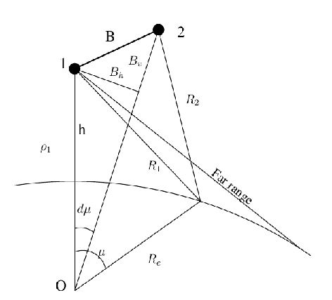
The basic configuration of InSAR is shown in figure D.1.
Figure D.1:
Geometric configuration for InSAR.  are the range
vectors to the corresponding resolution element. The statevector of
the reference satellite is denoted by
  . (h denotes the
satellite height,
  the location angle of the co-registered
resolution cell in the interferogram.)
 |
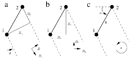
There are different representations for the baseline, see
Figure D.2.
Figure D.2:
Definition of the baseline parameters. (a)
parallel/perpendicular; (b) horizontal/vertical; (c)
length/orientation; Position 1 is the reference position.

 0 when
  , where
  is the corresponding slant
range. The angle
 is defined counter-clockwise from the
reference satellite (1), starting from the horizontal at the side of
the look direction.
 |
Conversions between baseline representations:
Table D.1:
Conversion between baseline representations
(note that the four quadrant arctangent should be used).
| |
![$ [B_h, B_v]$](img539.gif) |
![$ [B, \alpha]$](img540.gif) |
![$ [{B_{\perp}}, {B_{\parallel}}]$](img541.gif) |
![$ [B_h, B_v]$](img539.gif) |
- |
 |
 |
| |
- |
 |
 |
![$ [B, \alpha]$](img540.gif) |
 |
- |
 |
| |
 |
- |
 |
![$ [{B_{\perp}}, {B_{\parallel}}]$](img541.gif) |
 |
 |
- |
| |
 |
 |
- |
The baseline parameters can be computed when the statevectors of the
points M, S and P (master ,slave and point on surface) are known.
(The distance between the points x and y is denoted by
 ; and the sharp angle between two vectors x and
y by
 .)
.)
 |
(D1) |
 |
(D2) |
Now the perpendicular baseline has to be computed. The definition
states that
 is positive if the slave satellite is to the
right of the slant range line of the master. Which yields for a
mountain an increasing phase from foot to summit(?) We had some
trouble finding a simple expression to find out the correct sign but
at the moment we do something like the following.
 |
(D3) |
 |
(D4) |
 |
(D5) |
 |
(D6) |
 |
(D7) |
 |
(D8) |
 |
(D9) |
 |
(D10) |
 |
(D11) |
 |
(D12) |
 |
(D13) |


Next: Interferogram
Up: Definitions
Previous: Constants
Contents
Leijen
2009-04-14


![]() ; and the sharp angle between two vectors x and
y by
; and the sharp angle between two vectors x and
y by
![]() .)
.)

